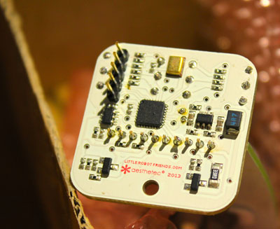
Most of the technical stuff on the robot happens on the ‘foot board’, the small square board attached to the base. On the bottom side of that board is the microcontroller, some sensors, some transistors, resistors, capacitors - lots of parts.
Battery Power
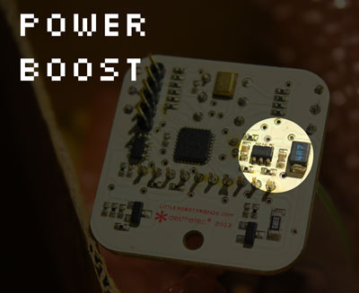
All these parts work together to make your Little Robot Friend do its thing, however they need electric power to make it happen. We’re powering the LRF with two AAA batteries in a parallel configuration. The voltage from these batteries are then ‘stepped-up’ from 1.2-1.5 volts to 3.3 volts. Everything on the Little Robot Friend is then powered from this 3.3 volt power source. When your battery gets down to around 0.85 volts, your Little Robot Friend will switch to a ‘hungry’ mode where your lights will dim and your speaker is muted. It will also flash red to tell you to replace the batteries! Sometimes the batteries are too low to even run in ‘hungry’ mode, so if your robot is having troubles, make sure you are using charged batteries.
Microcontroller Brain
The LRFs brain is a Atmel ATmega328p, the same microcontroller found in the Arduino Uno and lots of other Arduino-compatible hardware. It has an internal oscillator running at 8Mhz, a handful of analog-to-digital converting (ADC) inputs, a handful of pulse-width-modulating (PWM) outputs, 32K of program memory (for our instructions), 2K of data memory (for our temporary variables), 1K of EEPROM memory (for persistent variables that don’t change when the batteries are removed), and lots of other things. For more information, check out the product page over at Atmel.
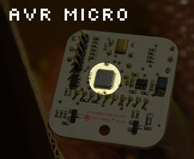
Here’s a table to show how we’re using the microcontroller:
| AVR | LRF | Description |
|---|---|---|
| PB0 | RGB_LEFT_GREEN | Driven by software PWM (Timer2) |
| PB1 | SPEAKER_OUT | Driven by hardware PWM (Timer0) |
| PB2 | RGB_RIGHT_RED | Driven by software PWM (Timer2) |
| PB3 | RGB_LEFT_BLUE | Driven by software PWM (Timer2) |
| PB4 | RGB_RIGHT_GREEN | Driven by software PWM (Timer2) |
| PB5 | RGB_RIGHT_BLUE | Driven by software PWM (Timer2) |
| PB6 | RESERVED | |
| PB7 | RGB_LEFT_RED | Driven by software PWM (Timer2) |
| PC0 | NEEDINESS | Personality resistor (read by ADC) |
| PC1 | HUMOUR | Personality resistor (read by ADC) |
| PC2 | HAPPINESS | Personality resistor (read by ADC) |
| PC3 | CHATTINESS | Personality resistor (read by ADC) |
| PC4 | ENTHUSIASM | Personality resistor (read by ADC) |
| PC5 | BRAVERY | Personality resistor (read by ADC) |
| PC6 | RESET | Hardware reset (pulled-up with 10K resistor) |
| ADC6 | MIC_IN | MEMs microphone (read by ADC) |
| ADC7 | LIGHT_IN | Ambient light sensor (read by ADC) |
| PD0 | SERIAL_IN | Serial input (TTL voltage level) |
| PD1 | SERIAL_OUT | Serial output (TTL voltage level) |
| PD2 | TOUCH_IN | Touch sensor active (digital input) |
| PD3 | IRDA_IN | Infrared phototransistor (digital input) |
| PD4 | IRDA_OUT | Infrared LED (output) |
| PD5 | TOUCH_SYNC | Touch sensor sync (output) |
| PD5 | BATT_VOLTAGE | Battery voltage (Analog comparator input) |
| PD6 | TEST_VOLTAGE | Test voltage for Battlow (Analog comparator input) |
RGB LED Eyes
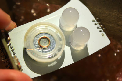
Your LRFs eyes are two diffused 10mm RGB LEDs with a common cathode. These bright LEDs feature three colours (red, green and blue) and require between 2.4 and 3.2 volts to illuminate. In order to save battery, we’re using a technique called pulse width modulation (PWM) to quickly flash the LEDs in such a way that they can appear at different levels of brightness and use less power. This is the same technique used to dim the lights in your house. By mixing the brightness level of the red, green and blue LED channels we can create a wide variety of colours.

Speaker Mouth
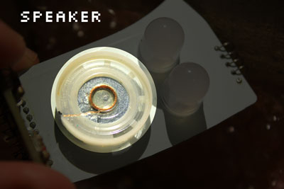
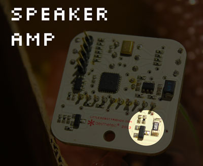
Your LRFs mouth is a 1/4W 8ohm mylar speaker. By using PWM, we can quickly pulse a signal sent a little coil in our speaker, which causes it to vibrate the mylar and make sound. The frequency of this sound can be increased or decreased by changing how long we’re pulsing that signal. This is called frequency modulation or FM (like an FM radio). Before the signal sent from the microcontroller reaches the speaker, it’s put through a small simple amplifier to ‘amplify’ its power. This increases the loudness of your robot. While we have control over the frequency of the sound, we don’t have the ability to dynamically change the loudness.
Touch Sensor
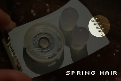
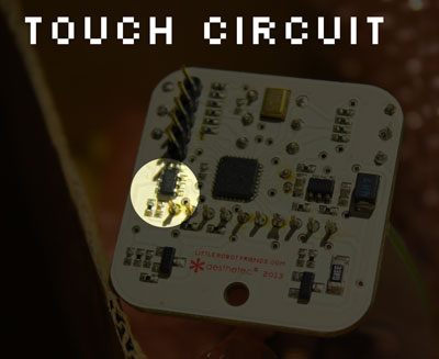
The top of your LRF has a small spring coil that we are using as the antenna for our touch sensor, that is actually located on the bottom of the foot board. It’s calibrated for direct human touch, or touch with another ‘conductive’ object. Most organic material with some water content can conduct electricity. Feel free to play around with different conductive objects to see how sensitive they are. You can also replace the spring hair with another conductive material like bare copper wire or a bare tin paper clip.
Light Sensor
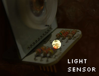
There is a small chip on the middle / top of the foot board. This is an ambient light sensor that changes its output voltage based on the amount of light in its nearby environment. We are reading this sensor using an analog-to-digital converter pin on our microcontroller. Using this sensor, we can detect if you’ve cupped your hands over the robot, if you’ve turned off the lights, or if you’re in a really bright environment like sitting in the sunshine.
Sound Sensor
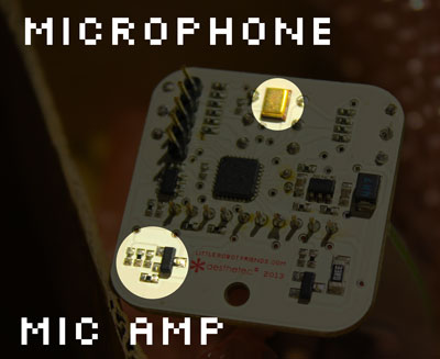
Located on the bottom of the foot board is a small rectangular gold-coloured chip. This is a MEMs-type microphone. These microphones are commonly found in mobile phones or other small electronics. There is a small hole on the top of the foot board that allows sound to travel into the sensor, however its not very sensitive and requires you to get quite close and loud with the sensor. We’ve done our best to amplify the signal coming from the microphone in order to increase its sensitivity, but we found that it could be too easily triggered by ambient sounds in the environment. If you’re keen, you can change the (very small) resistor values around the microphone amplifier to increase the sensitivity to a desired level, or play with the software library to increase sensitivity.
Infrared Chatting
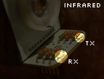
We’ve added two infrared chips on the LRF - located on the top / front of the foot board - to allow robots to chat with each other. One is an infrared LED (output), the other is an infrared phototransistor (input). We’re doing all the interpretation of the infrared signals in our code library, so you can play around with the code if you want to send and receive custom messages (like from remote controls). Our infrared chips are calibrated for the 890nm light spectrum and since they don’t have a filter to block other spectrums they can occasionally be triggered by sunlight or bright environmental light. So for best results, use the infrared aspect of your robot indoors.
Dock Connector (Serial Port)
The connector on the bottom of the LRF is for connecting your robot to our Hacker Dock or another USB-to-Serial device. It is a 5-pin 2mm spacing connector with the following signals:
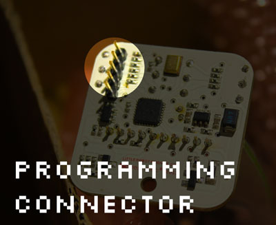
| Pin | Function | Description |
|---|---|---|
| 1 | 3.3V | Voltage from the robot (for reference, not powering things) |
| 2 | Ground | Ground signal (required for reliable communication) |
| 3 | Reset | Hardware reset for putting robot into programming mode |
| 4 | Serial In | Data sent from device to robot |
| 5 | Serial Output | Data sent to device from robot |
Personality Resistor Shoelaces
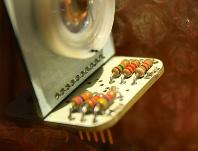
If you want to set the personality of your robot without any programming, we’ve created a way for you to do that. By picking one of five resistor values you can set a personality trait to be stronger or weaker. These resistors are read by our microcontroller using an analog-to-digital converter (ADC) pin. Check out this chart to see how the personality traits map to different resistor values:
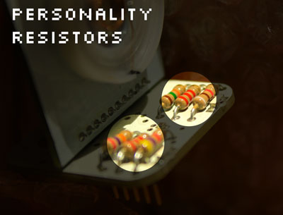
| Resistor Value | Trait 'Resistance' |
|---|---|
| 2.2K | Lowest |
| 4.7K | Low |
| 9.1K | Medium |
| 15K | High |
| 27K | Highest |
This may seem a little counter-intuitive, but think of it this way: If you want your robot to be happy, use a low-value resistor so lots of happiness can flow to your robot. For a more surly robot, resist the happiness using a high-value resistor. Makes sense?
We've also got a set of pre-defined characters that you might like that also unlock a unique signature expression. Here are the resistor values for each character:
| Personality | Bravery | Happiness | Enthusiasm | Neediness | Chattiness | Humour |
|---|---|---|---|---|---|---|
| Chatterbot | 4.7K | 4.7K | 4.7K | 27K | 2.2K | 4.7K |
| Divabot | 2.2K | 15K | 2.2K | 27K | 2.2K | 9.1K |
| Platobot | 4.7K | 15K | 27K | 2.2K | 27K | 27K |
| Rascalbot | 2.2K | 9.1K | 2.2K | 9.1K | 4.7K | 4.7K |
| Nannabot | 4.7K | 4.7K | 27K | 9.1K | 15K | 15K |
| Officebot | 15K | 15K | 15K | 4.7K | 15K | 9.1K |
| Partybot | 4.7K | 2.2K | 2.2K | 27K | 2.2K | 4.7K |
| Scaredybot | 27K | 9.1K | 4.7K | 4.7K | 15K | 15K |
| Jollybot | 9.1K | 2.2K | 4.7K | 15K | 4.7K | 2.2K |
| Evilbot | 2.2K | 27K | 4.7K | 15K | 9.1K | 15K |
Now you have a basic understanding of how the Little Robot Friend hardware works. Check out the next chapter, Firmware Basics, to get an overview of how the code library makes a robot do its thing.
